|
Setting Signal Data Sources
One-Line Diagram Kit allows you to set the following types of PMU signals as data sources for drawn objects, enabling those objects to show the corresponding signal data in real time:
-
Synchrophasor data
-
Calculated values such as power, power corridors, and angle differences
For example, you could draw an electrical object on a diagram and then map a corresponding PMU signal to display with that object.
To set a data source for a diagram object:
-
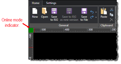
Make sure you are working in online mode.
-
If the free-form toolbox is not visible on the screen, open it by selecting the Toggle Toolbox command under the Settings tab.
-
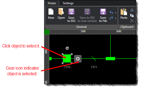
Select the object you want to set a data source for by clicking it in the diagram. You can select multiple objects to set a data source for at the same time by pressing the CTRL key while you click the objects.
-
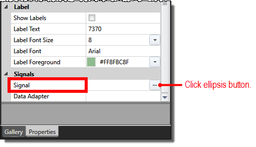
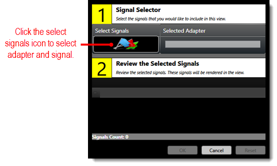
Under the Properties tab in the free-form drawing toolbox, click the ellipsis (...) button for the Signal property.
-
When the Signal Selector Editor screen opens, click the select signals icon in the Signal Selector section.
-
When the Data Point Selector screen opens, select an adapter and signal to use for the selected object. If you have a large list of signals, you can use a filter to find a specific signal.
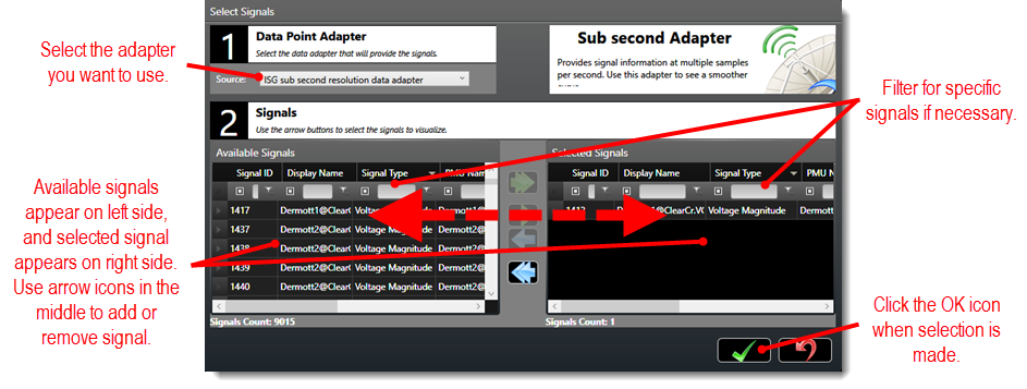
After you make your selection in the Data
Point Selector screen, click the OK icon (![]() )
to return to the Signal Selector Editor
screen.
)
to return to the Signal Selector Editor
screen.
-
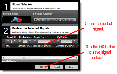
Click the OK button in the Signal Selector Editor screen to save your signal selection.
-
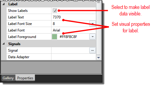
When you return to the properties toolbox, select the Show Labels, property check box to make the signal data visible in the diagram. You can also set other properties such as Label Text and Label Font Size to change the appearance of the signal information in the diagram.
-
Change the Data Feed Update Interval (ms) property as needed to adjust the adapter speed.
-
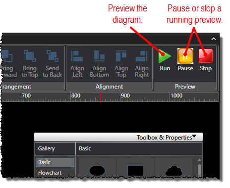
Preview the diagram if you would like to test your changes.