|
Setting Conditional Actions
One-Line Diagram Kit allows you to add conditions to drawn objects so that the objects dynamically change when specified conditions are met. For example, you could set an electrical object in a diagram to change color from yellow to red when the voltage exceeds a predefined threshold. You can set more than one condition for the same object so that multiple actions can occur under different conditions. For example, you could set multiple conditions so that the diagram object changes from green to yellow under one condition and then from yellow to red under another condition.
To set conditional actions:
-
If the free-form toolbox is not visible on the screen, open it by selecting the Toggle Toolbox command under the Settings tab.
-
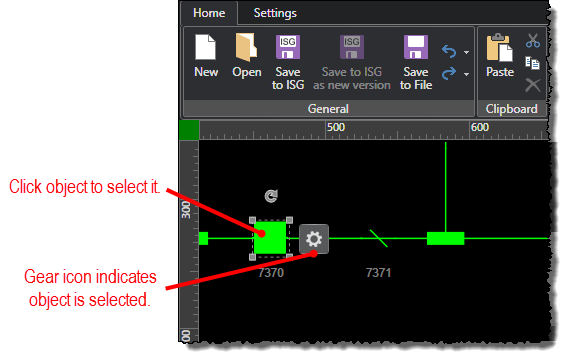
Select the object you want to set conditional actions for by clicking it in the diagram.
-
If a signal is not already set for the selected object, then set the signal data source you want to use. This is the data source on which the specified conditions will be based.
-
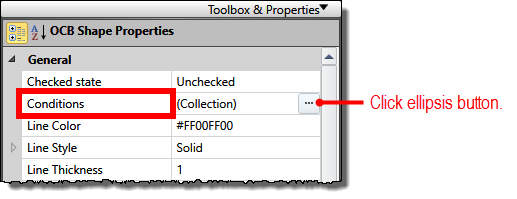
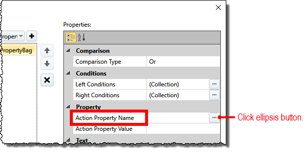
Under the Properties tab in the free-form drawing toolbox, click the ellipsis (...) button for the Conditions property.
-
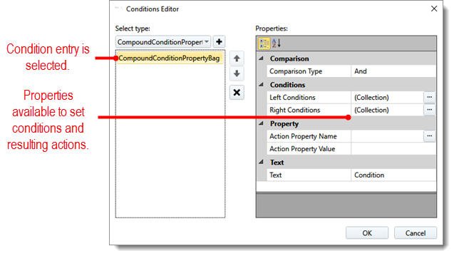
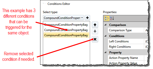
When the Conditions Editor window opens, click the + button next to the Select Type selection box to add a condition entry to the list. This is an entry you will use to specify the conditions and resulting action you want to take on the selected object.
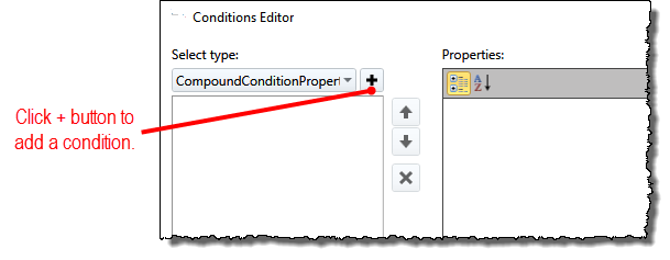
After the condition entry is added, it is selected in the list and its properties are available for you to specify conditions and resulting action.
-
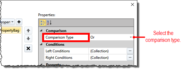
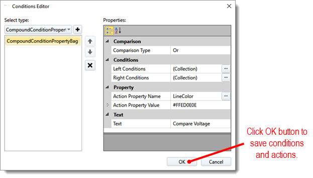
With the condition entry selected in the list, select And or Or for the Comparison Type property to use in evaluating the left and right conditions (left and right conditions are specified next):
-
And means that both the left and right conditions must be met for the condition to be triggered and the resulting action activated. If only one of the conditions is met, the action is not activated.
-
Or means that either the left or right condition can be met for the condition to be triggered and the resulting action activated. If only one of the conditions is met, the action is activated.
For example, to trigger a condition when voltage either drops below 210 kV or spikes above 260 kV, you would select Or.
-
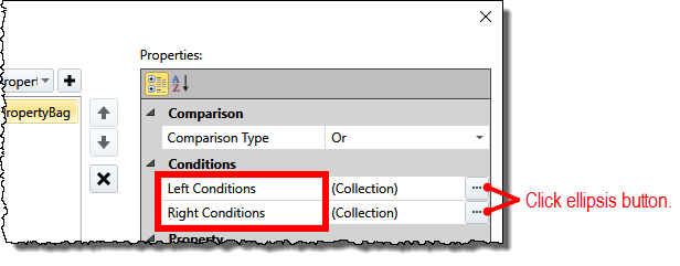
To specify the parameters of the condition, click the ellipsis (...) button for the Left Conditions or Right Conditions property (depending on which one you are setting). You can set both the left and right conditions or set only one of them. If you set only one of the conditions, the system ignores the Comparison Type property set in the previous step.
-
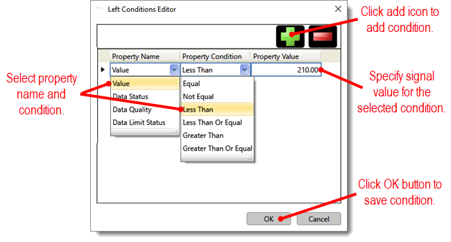
When the Left or Right Conditions Editor window opens, click the add icon (
 ) at the top of the window
to add a condition, and then specify the signal's property, condition,
and value that must be met for the resulting action to be activated.
For example, to trigger a condition when voltage either drops below
210 kV or spikes above 260 kV, you would specify the following:
) at the top of the window
to add a condition, and then specify the signal's property, condition,
and value that must be met for the resulting action to be activated.
For example, to trigger a condition when voltage either drops below
210 kV or spikes above 260 kV, you would specify the following: -
Left Condition: Signal Value to drop Less Than the value of 210.00
-
Right Condition: Signal Value to spike Greater Than the value of 260.00
These conditions work with the Comparison Type selection of Or (from the previous example) to trigger the specified action (action properties are specified next). The example above means the specified action will be triggered when the corresponding signal's value drops below 210.00 OR spikes above 260.00. You can specify conditions for the following property names:
-
Value: Value of the corresponding signal
-
Data Status: Value of the status flag associated with the PMU of the signal
-
Data Quality: Quality flag set by the data quality filter algorithm
-
Data Limit Status: Flag set by the engineering value check algorithm
-
Click the OK button to return to the Conditions Editor window.
-
To specify the action to take when the condition is met, click the ellipsis (...) button for the Action Property Name property in the Conditions Editor window.
-
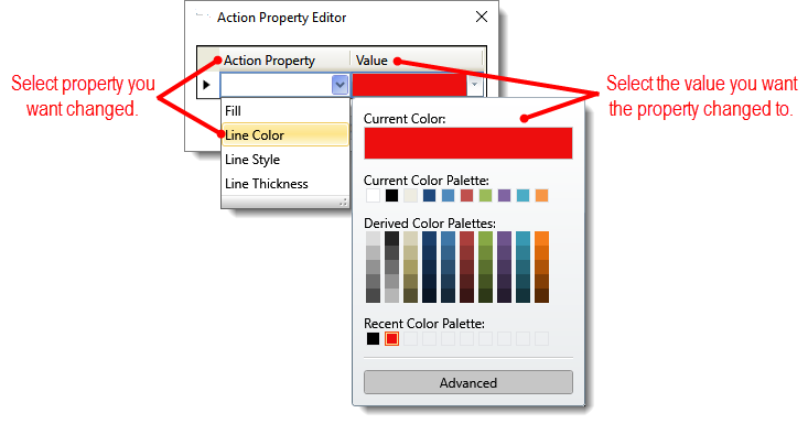
When the Action Property Editor window opens, select the property you want changed in the Action Property selection box, and specify the value you want the property to change to in the Value box. For example, to have the line color of a bus change to red when the corresponding conditions are met, you would select Line Color as the Action Property and select the color red as the Value.
-
Click the OK button to return to the Conditions Editor window. The action property and the corresponding value are updated in the Action Property Name and Action Property Value properties.
-
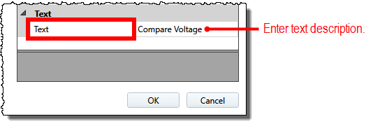
Optionally, in the Text property, enter text that will help you identify the condition. This text is simply a way for you to identify the purpose of the condition. It does not appear in the diagram.
-
Repeat steps 5-13 for any additional conditions you want for the selected object. If you need to remove a condition, click the X button.
-
Click the OK button in the Conditions Editor window to save the specified conditions and resulting actions.
-
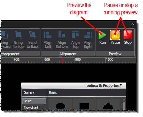
Preview the diagram if you would like to test your changes.