


|
Integration in RTDMS Client Application
Diagrams created in One-Line Diagram Kit can be saved to your ISG and then added as views for visualization in the RTDMS client application. These views can include system-level diagrams or substation-level diagrams.
Example of View with System-Level Diagram
The following example shows a system-level diagram added to an RTDMS client application dashboard, with synchrophasor data and breaker status (if available via ICCP/PMU Digitals) mapped to the diagram:
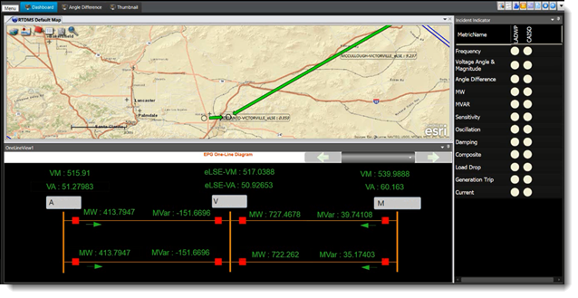
This example diagram view contains a three-bus system diagram created in One-Line Diagram Kit using the free-form drawing tools. The diagram includes substation names, buses, transmission lines, and circuit breakers. The voltage phasor measurements are mapped to the substations, and the calculated power flow signals are mapped on the corresponding transmission lines. Arrow icons along the transmission line represent the direction of power flows on the diagram view.
Example of View with Substation-Level Diagram
The following example shows an RTDMS client application display that contains a substation-level node-breaker diagram added to an RTDMS display, with synchrophasor data mapped to corresponding nodes:
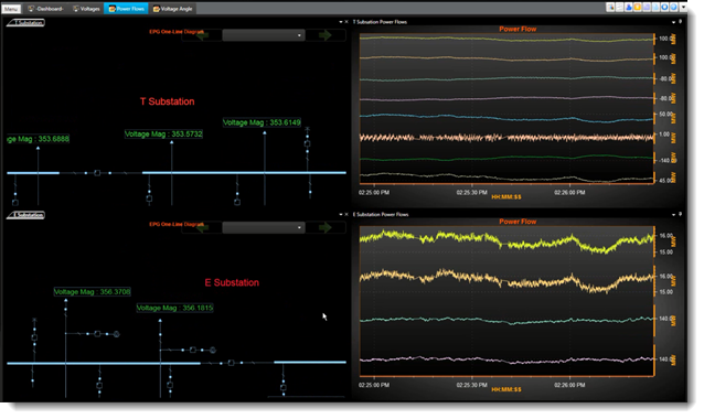
In this example, the T Substation and E Substation are added separately to the display as individual views. The voltage magnitude PMU measurement on each line-side is mapped to the corresponding nodes of the transmission lines.